Traction motors and transformers are the magnetic parts that appear to get all the eye, however the humble inductor/choke is simply as crucial a part in fashionable energy converters, and it has surprisingly profound results on efficiency, reliability and value. One other temptation for the bewildered design engineer (or one that’s simply quick on time—however isn’t that each one of us?) is that there are quite a few inductors/chokes out there COTS (Commercially Off The Shelf), which is usually not the case for transformers, and selecting a COTS half isn’t essentially a nasty possibility—specialist suppliers supply very high-quality magnetic parts, and probably for a lot lower than a bespoke part, even in manufacturing portions.
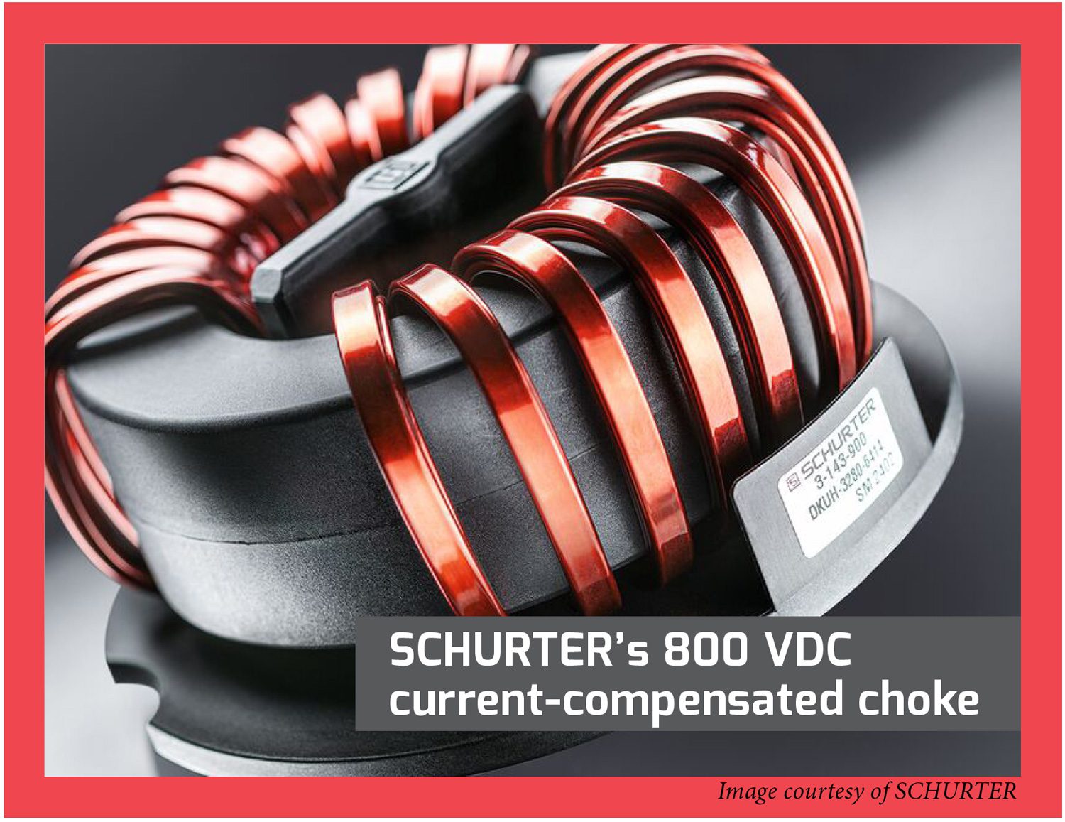
The common-or-garden inductor/choke is a crucial part in fashionable energy converters, and it has surprisingly profound results on efficiency, reliability and value.
Nonetheless, that doesn’t absolve the design engineer from verifying the suitability of a COTS part in a given utility, as the very last thing you need is for a part you barely vetted to grow to be an occult supply of inefficiency, unreliability, or that almost all dreaded of outcomes: to trigger the gadget to fail Electromagnetic Compatibility Compliance (EMC) testing.
Whereas a choke is technically a selected sort of inductor (one that may deal with important DC bias earlier than totally saturating), the time period is ceaselessly abused (e.g. the “widespread mode choke” present in just about all AC mains filters by no means sees DC, so it isn’t a choke). Subsequently, it’s most likely greatest to deal with the phrases inductor and choke as interchangeable. That stated, inductors are broadly used for 3 main features in EVs: in standard low-pass LC filter networks for producing (moderately) clear DC outputs in switchmode energy converters; in tuned (aka resonant) LC networks, both in explicitly-resonant converter topologies, or simply to cut back losses in the course of the switching transitions in PWM topologies (aka quasi-resonant or soft-switching); and in EMI filters for blocking the emission (or reception) of radio-frequency noise.
These functions place very completely different calls for on inductors, therefore the sooner admonition that simply because you will get one COTS doesn’t essentially imply it would work all that effectively within the particular a part of the circuit you’ve dropped it into.
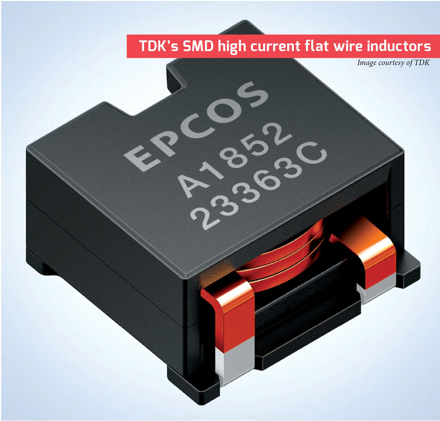
The edgewound flat wire building is most well-liked at greater present rankings, particularly at average switching frequencies below 150 kHz.
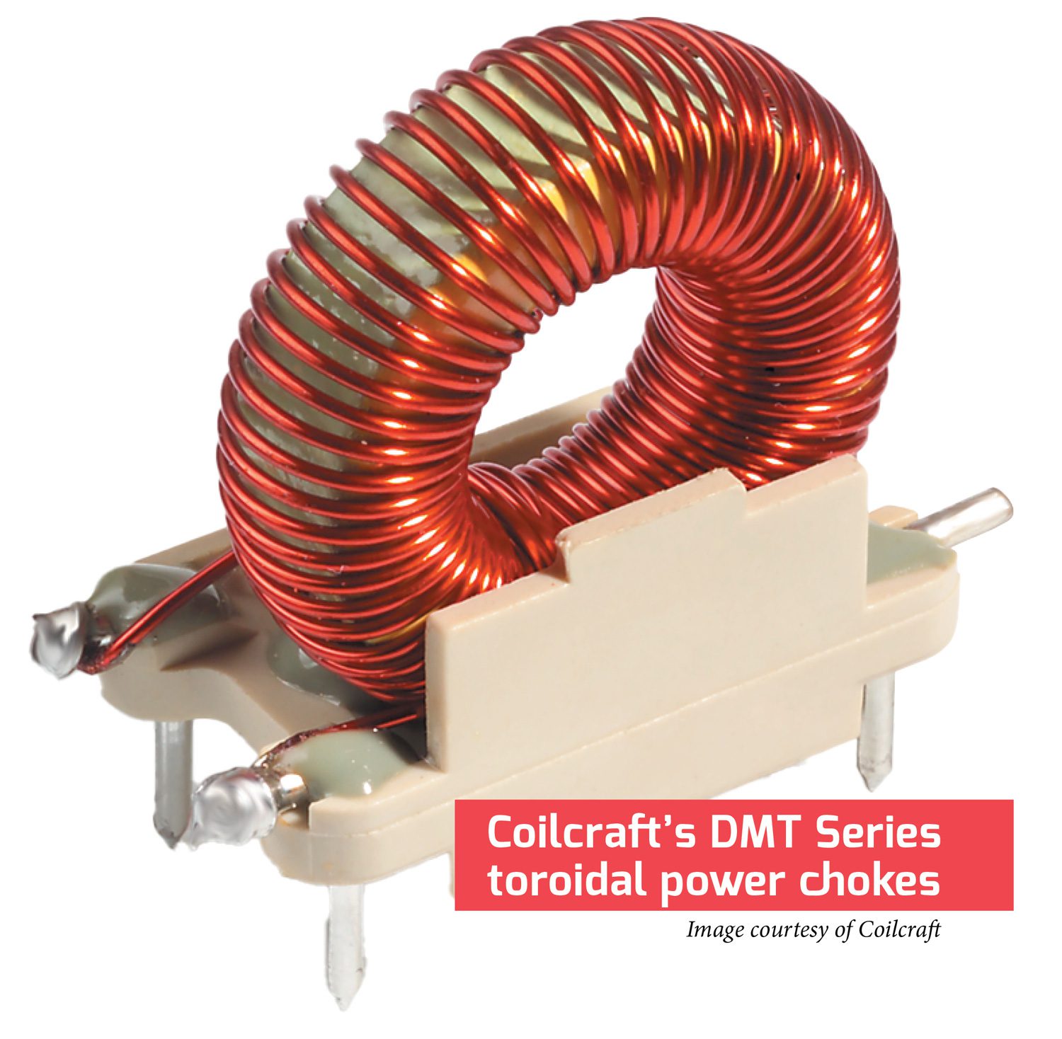
The overwhelming majority of inductors utilized in energy converters, no matter topology, could have a ferromagnetic core—that’s, not be a easy coil of wire—and more often than not that core will likely be in a form such that the magnetic flux from the windings can comply with a totally closed loop (a toroid is the traditional instance right here). The latter characteristic won’t be essential for the functioning of the circuit, however it’s key if you wish to go EMC compliance testing, as a result of any flux traces that don’t escape the core are sure to trigger noise points elsewhere.
For instance, the now-ubiquitous drum-core SMT inductors which may look ideally suited to be used in low-power auxiliary converters don’t have a closed magnetic loop—the flux traces should go by means of air to finish their circuit—which might flip these little devils into miniature “EMI cannons” (an precise sobriquet I’ve heard used to explain them). Selecting a core form that closes the flux loop is just a part of the battle, although, as different parameters and design objectives are sometimes mutually unique, so compromise is inevitable. For instance, core supplies which are optimized for low AC losses (hysteresis and eddy) are inclined to have a decrease saturation flux density, so would require extra core space for a given inductance and energy dealing with capacity, which in flip will increase the quantity of stray capacitance, and so forth.
The primary perform of the sequence inductor in an LC output filter is to cut back the quantity of AC ripple seen by the shunt capacitor that follows it with out additionally being overwhelmed by the DC flowing by means of it. This will increase the significance of minimizing the DC losses of the windings over the AC losses of the identical, and of the core.
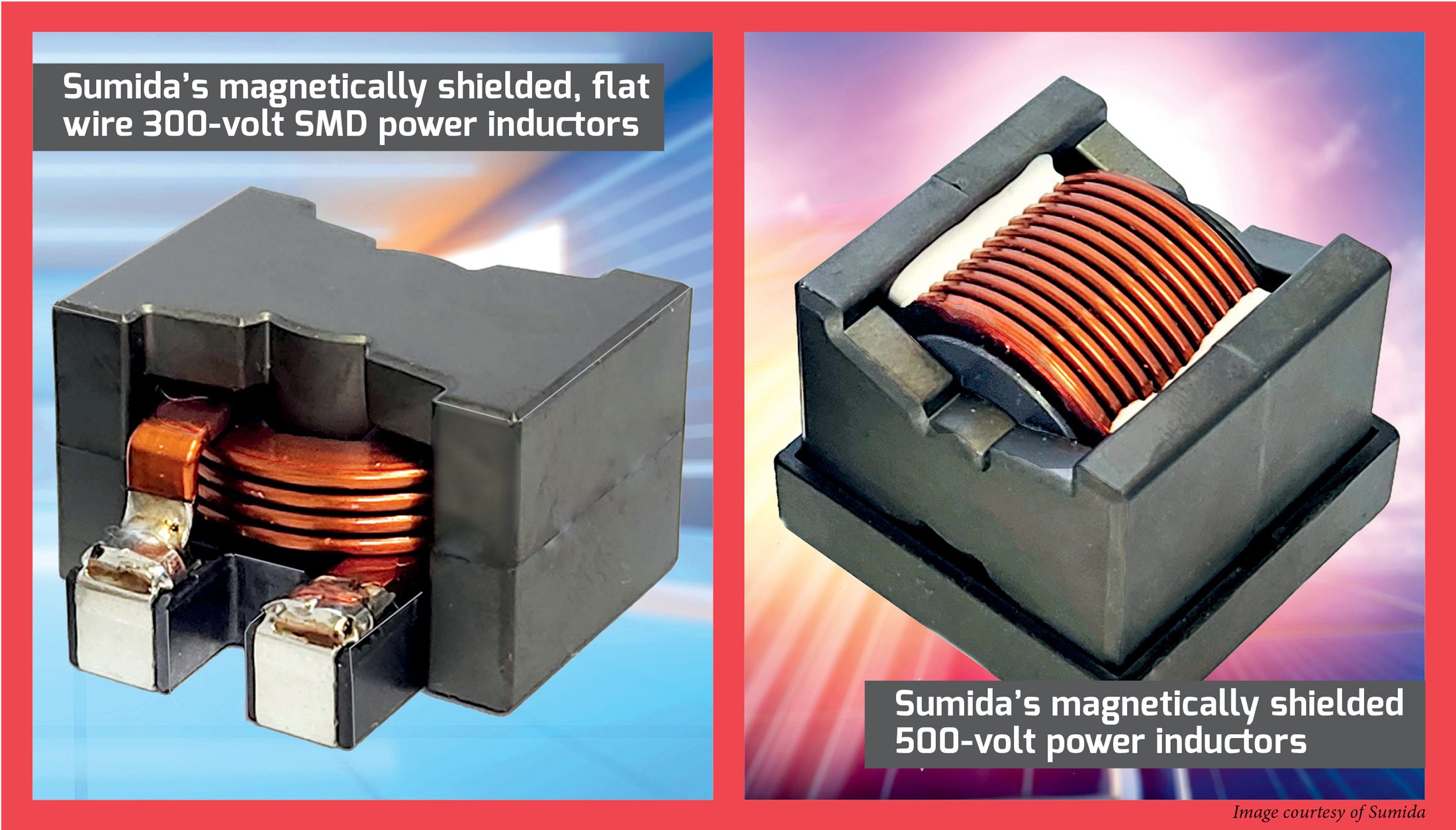
A single layer of standard magnet wire (utilizing a number of strands in parallel if essential to attain the goal present score) will usually work effectively. Additionally attainable (on the expense of upper stray capacitance) is the edgewound flat wire building—this sort is most well-liked at greater present rankings, particularly at average switching frequencies (below 150 kHz), although it tends to have the next stray capacitance. As for the core itself, nearly any “energy materials” will work right here (versus supplies optimized for RF/tuned circuits or, worse, EMI filters), so long as there may be both an express or distributed air hole to stop saturation from the DC bias.
The hole is express (i.e. a literal hole) in ferrite cores, and cores with normal hole lengths can be found COTS from most producers, although there may be little penalty in specifying a customized hole so long as you purchase sufficient of them, and might wait to have them machined, because it takes diamond tooling to chop ferrite. Be aware, nonetheless, {that a} discrete hole will likely be a potent emitter of EMI, so it would nearly actually should be shielded by the windings (at the price of elevated AC losses in them), therefore the hole is sort of all the time lower into the middle leg of (for instance) pot- or E-shaped cores; shimming the core halves may be wonderful for prototyping, however not for manufacturing.
Cores utilizing a mixture of powdered metallic and a binder usually have a distributed hole which will be adjusted by the producer by various the ratio of the 2. As with ferrites, there are a number of normal gaps out there (specified not directly by way of the permeability), although right here there’s a a lot greater price penalty for customized values, so one is strongly suggested to stay with the usual choices.
Inductors utilized in tuned (resonant) LC networks aren’t subjected to any DC bias, however are usually operated at a lot greater frequencies, that being one of many predominant objectives of resonant (or quasi-resonant) operation, in any case. Consequently, quite extra emphasis is positioned on minimizing the AC losses in each the core and the windings over merely minimizing the winding resistance, however with one main caveat: the circulating present in a fully-resonant converter working close to resonance will likely be significantly greater than the precise load present (a number of instances greater, maybe), so winding resistance shouldn’t be utterly ignored.
Eddy present losses are a perform of each core materials and its building—the next bulk resistivity and a minimally thick dimension assist essentially the most.
The core losses are the results of hysteresis, or the trouble expended in flipping the magnetic domains backwards and forwards, and eddy currents, which come up from currents being induced into the core regular to the magnetic flux path. Hysteresis losses are fully a perform of the core materials. Ferrite and low-mix powdered iron carry out the perfect, as molypermalloy powder (MPP) and different powdered metallic mixes commerce greater losses for the next permeability worth and saturation flux density.
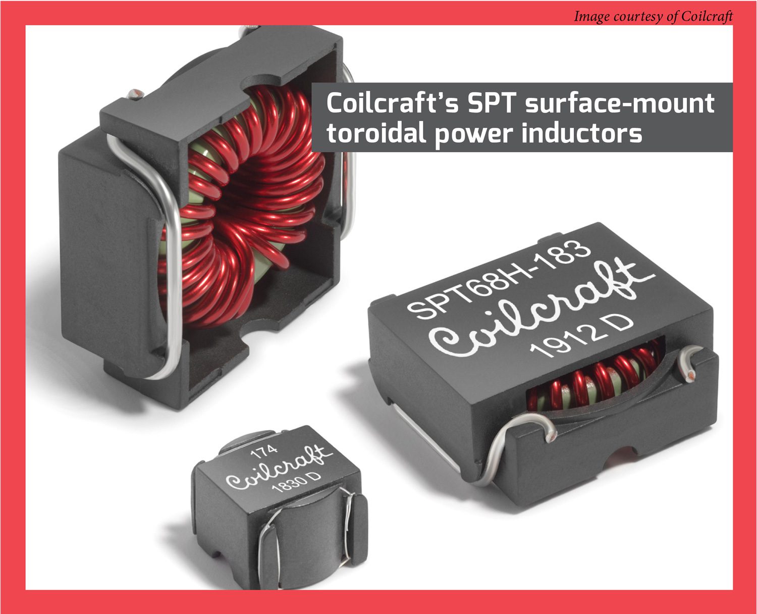
Eddy present losses are a perform of each core materials and its building—the next bulk resistivity and a minimally thick dimension assist essentially the most. After all, the bottom core losses outcome from having no core in any respect, and this would possibly very effectively be an possibility at frequencies above 500 kHz or so, although in case you don’t need this inductor to be an EMI cannon then it will nonetheless be greatest to make it toroidal in form.
The winding building for resonant inductors is quite tougher to optimize from a losses-vs-costs perspective, as a result of the widespread and low-cost strategy of twisting collectively a number of smaller magnet wires to get the mandatory present score won’t carry out practically so effectively in a resonant utility resulting from pores and skin and proximity results. Pores and skin impact is a phenomenon during which eddy currents induced right into a wire by the very high-frequency present it’s carrying pressure stated present into a hoop, with no present flowing within the heart, and this impact scales with the sq. root of frequency and the sq. of the diameter. For instance, the utmost frequency a #18 AWG wire (~1 mm diameter) can carry earlier than pores and skin depth begins to have an effect on it’s ~17 kHz, and this drops to a mere ~4.2 kHz for #12 AWG (~2 mm diameter).
An enormous variety of strands will likely be wanted to reduce pores and skin impact losses above 200 kHz or so, however except every strand spends the identical period of time (so to talk) going through the core and the wiring floor, proximity impact begins to dominate the losses (that is principally pores and skin impact arising from the magnetic fields from adjoining winding layers). Each pores and skin and proximity results will be alleviated with Litz wire, which consists of many (as much as lots of!) of individually insulated strands which are woven in such a means that every of them frequently adjustments its place between the middle and the perimeter of the wire.
There are sensible limits to how far this idea will be taken, nonetheless, as the price of Litz goes up with strand/bundle rely, whereas the person strands will grow to be too small to face up to the weaving and bundling course of in some unspecified time in the future (the same old cutoff is round #44 AWG). There are additionally extra refined causes to maintain the strand rely down, corresponding to an growing ratio of insulation to copper, and the truth that proximity impact occurs between every strand and every bundle of strands (albeit to not the identical diploma as between precise winding layers).
The upshot of all that is that it’s going to usually be extra economical general to go up a step or two in core dimension simply to cut back the variety of turns required to attain the goal inductance, and particularly to maintain all of the turns in a single layer (which additionally dramatically reduces the stray capacitance of the winding). Even so, operation at >200 kHz or so will nearly actually require Litz, so price range for that price enhance accordingly.
It’s going to usually be extra economical general to go up a step or two in core dimension simply to cut back the variety of turns required to attain the goal inductance, and particularly to maintain all of the turns in a single layer—which additionally dramatically reduces the stray capacitance of the winding.
The ultimate utility for inductors is EMI/noise filtering, and right here excessive AC losses in each the winding and core are extra of a characteristic than a bug, and going with a COTS part may be the only option. In case you are rolling your personal—or simply to raised choose a COTS part—then minimizing the stray capacitance of the winding is a comparatively greater precedence than anything, as this capacitance is a chief vector for high-frequency noise to bypass the inductor, defeating its very goal.
A single layer winding with a single magnet wire of applicable gauge for the present is the popular building right here. If the EMI filter inductor should carry appreciable DC or low-frequency (i.e. mains) AC present for its dimension—and this may very well be on the order of some mA for a signal-level inductor—then the identical design tips as defined above for DC-biased chokes will apply, although with way more emphasis on using a closed-form core form in order that these filter chokes doesn’t grow to be impromptu EMI cannons.
RF noise usually manifests on all wires passing by means of an enclosure, so common-mode filtering will likely be simpler than particular person filters for every energy and sign line (i.e. in regular or differential mode). That is most simply achieved by placing all the windings for a associated group of wires—together with their floor return—on a single core (e.g. the AC mains energy inlet, sign traces to the motor encoder, throttle pot, and so on).
The windings will seem in sequence for common-mode present, however nearly disappear for normal-mode present. The latter may very well be a minor difficulty in that some inductance should still be desired for differential-mode filtering, during which case purposefully establishing the windings to have excessive leakage inductance (e.g. by bodily separating them) will show helpful.
The ever present toroidal common-mode choke present in virtually each AC mains filter embodies all of those rules—the toroidal core is a closed kind, so it emits nearly zero EMI, and the windings include a single layer of a single magnet wire wound on reverse sides of the core, leading to excessive AC losses, the minimal attainable distributed capacitance, and comparatively excessive leakage inductance, with some differential-mode filtering thrown in at no cost. Most COTS common-mode chokes will already be listed/authorized with the related security businesses as effectively, making them an much more compelling alternative over bespoke parts.
This text first appeared in Challenge 71: January-March 2025 – Subscribe now.